Lorber Residence
Vista, CA
Residential remodeling presents unique challenges in that they involve investigating and, on occasion, modifying existing structural elements. One of the more costly elements to modify is the foundation. While existing foundations are capable of supporting more load than originally intended, this is usually only if the loads are applied uniformly along the length of the footing such as supporting roof rafters or floor joists.
A remodel often requires concentrated loads. These loads are created typically in two ways:
- The removal of a bearing wall perpendicular to an existing footing. This bearing wall would be replaced by a beam supported by posts.
- Anchorage at the ends of new shear walls.
A common approach in the analysis of the existing footings for these concentrated loads is to distribute the load through the footing at a 45 degree angle to the bottom of the footing. The resulting soil bearing pressure is compared to the allowable soil bearing pressure. If the resulting soil bearing pressure exceeds the allowable, an underpinned pad footing would be required.
At Allen Designs, we take the analysis a step or two further in order to reduce the number of underpinned pad footings.
- Modeling the existing footing
When the analysis considers distributing the concentrated load through the footing at a 45 degree angle, it is normally assumed the load is transferred directly to the soil putting no forces on the footing. Often, this is a conservative approach.
An alternative method is to model the footing using finite element analysis (FEA) to analyze the entire wall footing. It is intuitive that the load will be distributed somewhat, depending on the stiffness of the footing and the stiffness of the soil. Even though an existing one story footing is not very strong compared to a new footing, it still has some strength and is capable of providing some load distribution. This analysis approach is more time consuming and can result in higher engineering fees. However, we have now developed templates which reduce the time such that the engineering using this approach takes no more time than the method previously described. This approach saves both time and money.
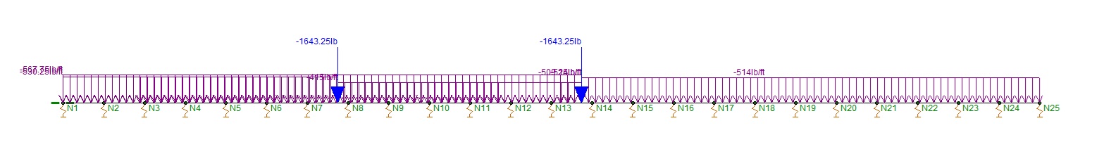
Finite Element Model of Existing Footing
(note spring supports representing the soil)
- Including openings in shear walls
It is a normal practice to analyze shear walls as individual, full height segments. This approach requires hold downs at the ends of each segment.
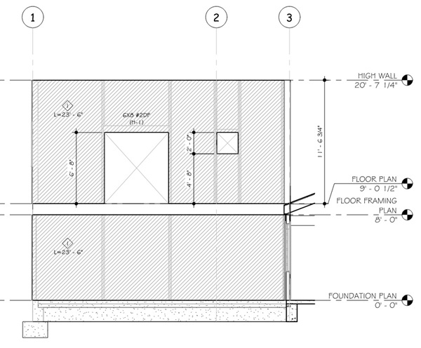
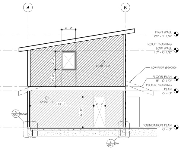
An alternative method of analysis is to consider the entire wall as a shear wall including the openings. This approach not only allows for a longer shear wall analytically (in reality, the entire wall will be sheathed anyway), then reduce the capacity based on the openings. The example below has very few openings, but this methodolgy will work with larger and more openings than what is shown below.
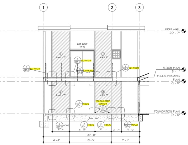
The advantage of this approach is that hold downs are only required at the ends of the shear wall, not at the ends of each individual segment. Since the shear wall is longer, the uplift force at the ends of the shear wall is less. In the example below, Grid Lines A and B are bearing walls supporting the roof rafters and floor joists which provide adequate resisting dead loads such that, based on the analysis, no hold downs are required at all. However, it may be prudent to provide nominal anchorage to ensure high performance of the lateral force resisting system.
An analysis using this method normally takes more time (= higher engineering fee), but, at ALLEN DESIGNS, we have developed templates which makes the process more efficient.
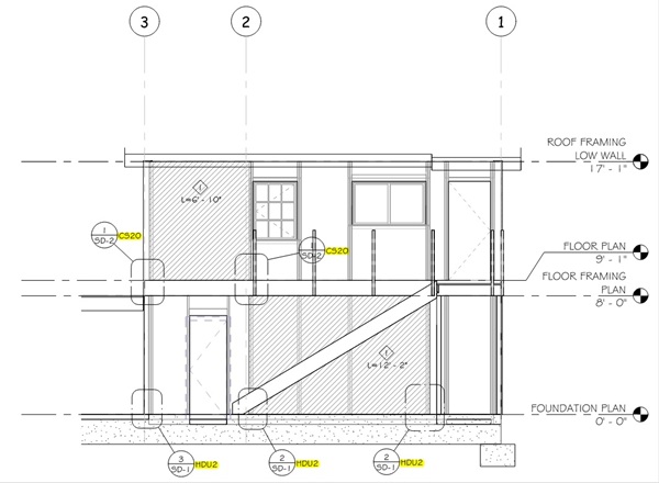
A comparision is illustrated below. The "Before" figures represent the shear walls analyzed as full height, segmented walls. The "After" figures represent the entire wall analyzed as shear walls which incorporate openings. The highlighted elements represent the hold downs eleminated by considering the entire wall as a shear wall considering the openings.
| Before | After |
 |
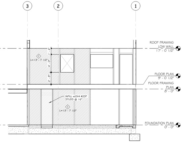 |
Framing Elevation Grid Line A
 |
 |
Framing Elevation Grid Line B
 |
 |
Framing Elevation Grid Line 3